RF Noise and Filters: Why Your Gateway Stops Hearing Distant Devices
The Gateway That Went Half Deaf
Everything looks fine. The gateway is online, the network server shows it connected, packets keep arriving. What changed is that they arrive only from the near half of the fleet. Sensors in the next building still report every fifteen minutes. The ones at the far end of the site went quiet, first intermittently, then for good, and the device list fills up with things last seen three days ago.
Nothing broke. Nobody moved an antenna, the devices are healthy, and their batteries are full. What happened is that the gateway's noise floor came up, and a receiver that works below the noise floor loses range one decibel at a time, silently, with no error anywhere in the logs.
This is receiver desensitization. It is the most common invisible failure in LoRaWAN, it is almost never diagnosed correctly on the first attempt, and it is usually blamed on the devices.
Why a Gateway Lives Below the Noise
The arithmetic explains both the magic and the weakness. Thermal noise in a 125 kHz LoRa channel sits at about -123 dBm. A gateway front end adds a few decibels of its own noise, call it 4 dB, which puts the noise floor around -119 dBm. LoRa at SF12 demodulates a signal roughly 20 dB below that noise, so the datasheet sensitivity of a modern concentrator lands at about -139 dBm. That is not marketing. It falls straight out of the numbers.
Notice what that makes the gateway. It is not a receiver that ignores noise; it is a receiver whose entire performance is defined relative to the noise. Sensitivity is not a property of the hardware alone, it is a property of the hardware plus its environment, and the environment is the part nobody specifies.
A LoRaWAN gateway hears signals about 20 dB below the noise. That is the whole trick, and it is also the whole vulnerability: every decibel the noise floor rises comes straight off your sensitivity, one for one. Ten decibels of unwanted energy costs you well over half your range, and nothing in the log will say so.
Worse, the gateway antenna you carefully mounted for maximum coverage is exactly as good at hearing a cell site as it is at hearing your sensors. Height and gain are neutral. They amplify the problem and the signal equally.
What Actually Raises It
Three different things raise a gateway's noise floor, and they have three completely different answers. Getting the diagnosis right is most of the work, because a filter fixes exactly one of them.
Transmitters that were there before you arrived
A concentrator front end is wideband by design. The low-noise amplifier sees everything the antenna delivers before any channel selection happens, so a strong signal that is nowhere near your band can still compress that amplifier, force the gain control to back off, and generate intermodulation products that land inside your channels. The interferer never has to be on your frequency. It only has to be loud.
Every regional plan has neighbours, and they are rarely quiet ones. EU868 is a narrow slice wedged between LTE Band 20 uplink, which ends at 862 MHz, and the GSM/LTE Band 8 uplink starting at 880 MHz with its downlink at 925-960 MHz; near a railway, GSM-R adds transmitters at 876-880 and 921-925 MHz. US915 occupies the 902-928 MHz ISM band with high-power paging transmitters immediately above it at 929-932 MHz, SMR services around 935-940 MHz, and cellular downlink up to 894 MHz just below. AS923 and KR920 countries work with a few megahertz of guard band before mobile allocations on either side. CN470 shares 470-510 MHz with terrestrial television, which means broadcast transmitters measured in kilowatts. AU915 and IN865 each have their own neighbours worth checking before choosing a site.
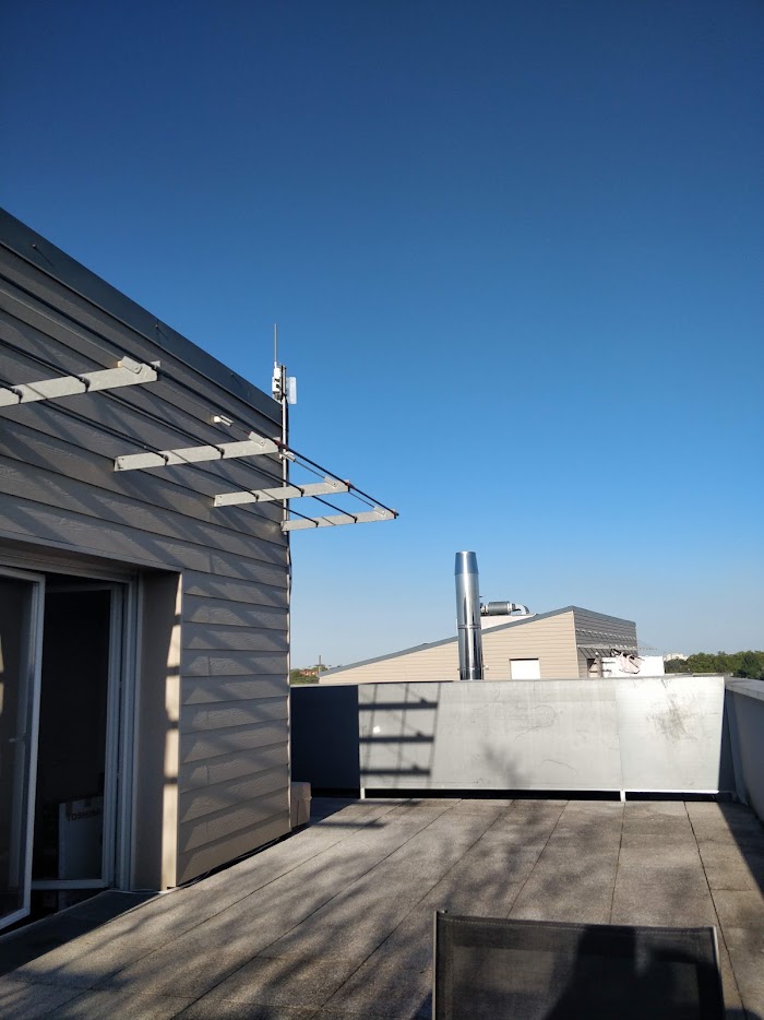
None of this matters at ground level in a field. It matters enormously on the rooftop or the telecom mast where you actually want the gateway, because those are the same places the other operators wanted, and their transmit power is four or five orders of magnitude above your sensors'.
The installation you built yourself
The second source is usually the biggest, and it is entirely free to fix. Switch-mode power supplies, PoE injectors, LED drivers, USB 3.0 ports, variable-frequency drives on a factory floor, and MPPT solar charge controllers all radiate broadband hash, and a solar or mesh relay build tends to put a switching regulator a few centimetres from a concentrator. So does the host board itself: a Raspberry Pi under a concentrator HAT is a small but real noise source, which is why our portable mesh relay build keeps the antenna as far from the Pi as the form factor allows.
Self-inflicted noise has a signature worth knowing. It is broadband rather than a discrete carrier, it does not vary with time of day the way human traffic does, and it disappears when you unplug the offending device. Before you buy a filter, spend an hour switching things off one at a time.
Other traffic inside your own band
The third source is legitimate traffic on your own frequencies: other LoRaWAN networks, wireless M-Bus meters, alarm systems, and a growing population of unlicensed devices sharing the same allocation. This one deserves a clear statement, because it is where most filter money is wasted.
No filter helps here. A bandpass filter passes your band by definition, so anything already inside it passes too. In-band congestion is a different discipline: channel planning, gateway placement, spreading factor discipline, and airtime budgeting. A traffic analyzer that shows you what else is transmitting in your area answers this question. A filter does not.
Proving It Before You Buy Anything
The symptom pattern is distinctive once you know it. Nearby devices work perfectly while distant ones fail, which rules out the network server and the backhaul. Downlinks still reach devices that cannot be heard, because the device's own receiver is not the one that is deaf. ADR steadily pushes devices to higher spreading factors, so the same sensors that ran SF7 last year now sit at SF10 or SF12 and burn battery doing it. Two identical gateways on identical firmware have wildly different reach. Packet loss follows a daily or weekly rhythm, which points at human activity rather than physics.
Confirming it takes three measurements. Read the per-channel noise floor your gateway already reports, since most concentrator statistics expose it and few people look. Then put a spectrum analyzer or an inexpensive SDR at the antenna port and sweep far wider than your band, several hundred megahertz either side, because the transmitter hurting you is by definition one you are not looking at. Finally, run a controlled reference test: a known device at a fixed distance and a fixed spreading factor, with RSSI and SNR logged before and after each change you make. Coverage claims that are not measured are guesses, which is the same argument behind a proper range assessment.
Fix things in cost order, because the cheap fixes are also the big ones. Separation and height first, since a few metres of vertical distance from a co-sited panel antenna buys more isolation than any filter. Then your own noise: shielded cable, better grounding, moving the switching supply, ferrites on DC runs. Then connectors and feedline, where a badly terminated N-type quietly costs several decibels and is the first thing to check during gateway onboarding. Only then a filter. And an external low-noise amplifier last of all, because a bare LNA in front of an overload problem amplifies the interferer along with everything else and makes desensitization worse, not better. If you fit one, the filter goes in front of it.
Two Filters, One NanoVNA
A bandpass filter goes between the antenna and the gateway and attenuates everything outside your band while passing what you need. Its cost is insertion loss, and because a LoRaWAN gateway transmits and receives through the same port, you pay that loss twice: once as reduced sensitivity on the uplink, once as reduced radiated power on the downlink.
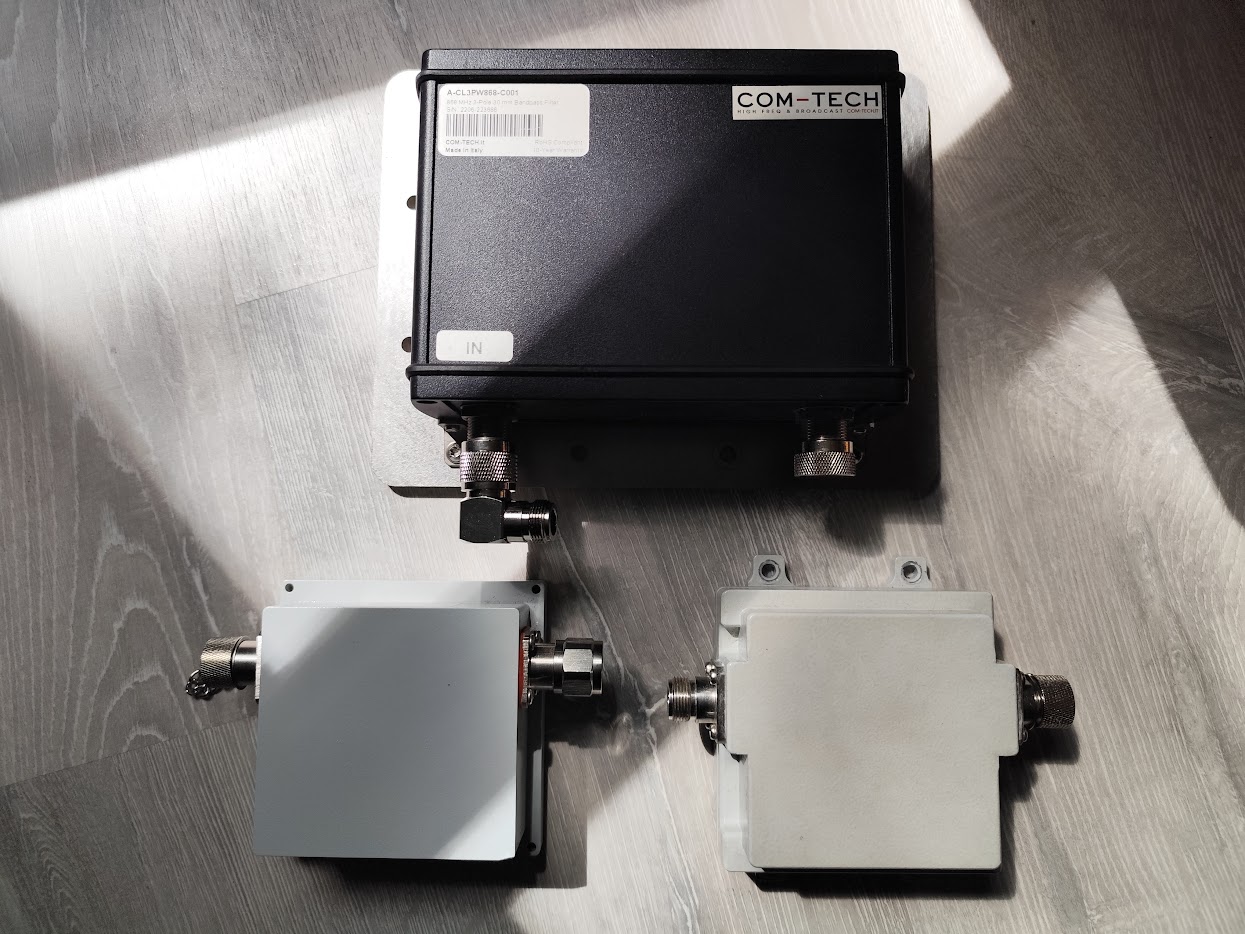
That makes insertion loss the number worth measuring rather than trusting. Here are three filters for the 868 MHz band, all swept on a NanoVNA-F V2 centred at 868 MHz with a 300 MHz span.
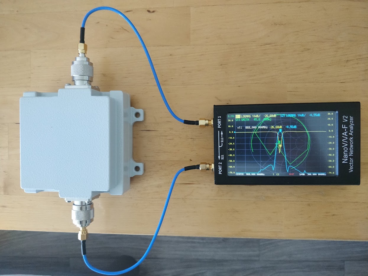
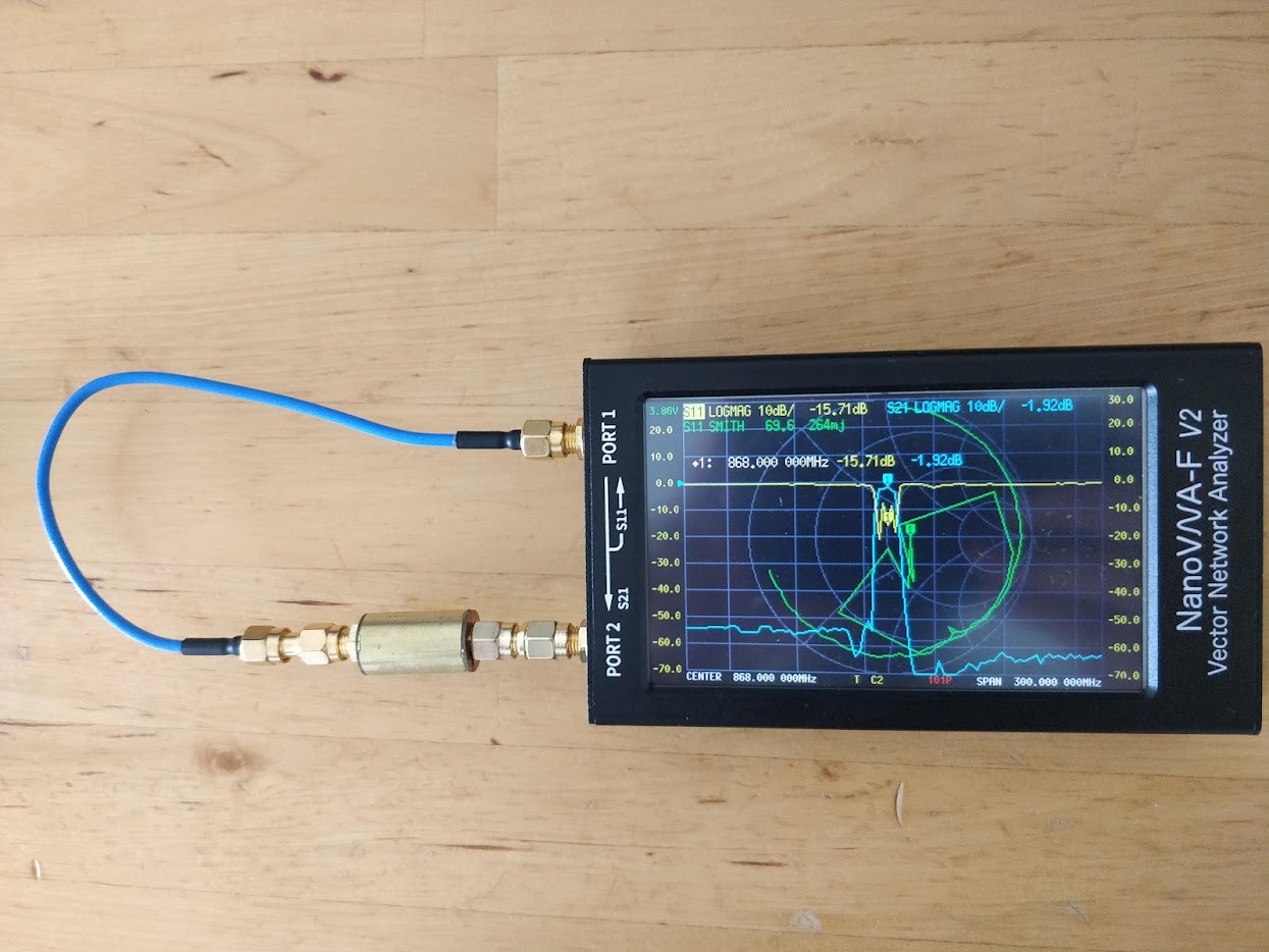
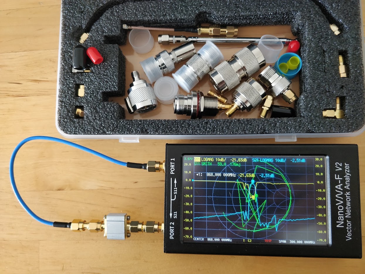
| Measured at 868.000 MHz | Cavity filter | SAW filter | Second SAW |
|---|---|---|---|
| Insertion loss (S21) | 0.55 dB | 1.92 dB | 2.51 dB |
| Return loss (S11) | 26.68 dB | 15.71 dB | 21.63 dB |
| VSWR | 1.10 | 1.39 | 1.18 |
| Size | palm-sized cast housing | inline barrel | small metal block |
Three traces, three honest results. S21 is what gets through, so the closer to 0 dB the better. S11 is how well the filter matches 50 ohms, and a poor match both wastes transmit power and degrades the noise figure of what follows it.
The 1.37 dB between the cavity and the better SAW is easy to underestimate. It lands twice, once as sensitivity on the way up and once as radiated power on the way down, so the round trip gives up 2.7 dB. In distance terms each direction shrinks by roughly 10 to 17 percent depending on how lossy the environment is. Put differently: choosing the wrong filter can cost more coverage than the interference you bought it to fix.
Two cautions about reading sweeps like these. Calibration is the entire measurement, so run a short-open-load-through calibration at the end of the exact cables you will use, over the exact span you will sweep, or the numbers mean nothing. And both stopbands here bottom out around -60 to -70 dB, which is the dynamic range of the instrument rather than the performance of the filter. A handheld VNA tells you insertion loss and match with real confidence; it cannot tell you how deep a good filter's rejection truly goes, and it says nothing at all about power handling.
Cavity or SAW
The cavity filter is a mechanical resonator: metal, air, and precise dimensions. It is the right answer wherever the interference is serious, because it gives up almost nothing in the passband, handles transmit power without complaint, holds its response across temperature, and rejects harder the further out you go. It costs more and it is bulky, and both of those are usually acceptable on a mast where a rack of other people's transmitters is the reason you are there in the first place.
The SAW filter is a surface acoustic wave device, small enough to be an inline barrel and cheap enough to fit as insurance. Its skirts are impressively steep for the size, which makes it attractive when the offender sits close to your band edge. The trade is one to three decibels of insertion loss, a modest sensitivity to temperature, and a power rating that is genuinely worth checking: plenty of SAW parts are specified well below the +27 dBm a gateway can transmit, and the filter sits in the transmit path too.
So the decision is mostly about the site. A rural or residential gateway with no strong neighbours does not need a filter, and fitting one there simply donates a decibel or two of range for nothing. A shared rooftop or telecom mast with cellular or broadcast equipment justifies a cavity, and the 0.5 dB it costs is cheap insurance. A compact, portable, or solar relay where size, cost, and mounting all matter is exactly where a SAW earns its two decibels. Cascading filters is rarely the answer, since the losses add and the second one seldom buys what the first did not.
One more check that catches people out: verify the passband actually covers your whole frequency plan. Some 868 MHz parts are centred narrowly enough to clip the edges of the 863-870 MHz band, and US915 needs a full 26 MHz of clean passband from 902 to 928. A filter that improves your noise floor while attenuating your own top channels has not helped you.
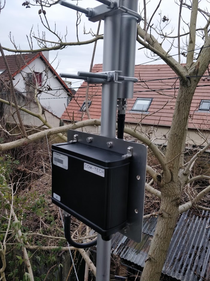
Mount it as close to the antenna as the installation allows, weather-sealed, on N-type connectors with a proper drip loop, and remember that anything in front of the filter is still unprotected. A filter at the bottom of thirty metres of feedline still works, but it also means the feedline loss lands ahead of it.
The Cheapest Filter Is the Antenna and the Mast
Two things reduce interference before any component does, and both are free at design time.
The antenna is the first filter in the chain. A resonant antenna cut for your band has useful rejection built in, whereas the broadband multi-band antennas sold cheaply for LTE will happily deliver every cellular signal in town straight into your front end. Specifying the right antenna costs nothing extra and quietly solves problems you then never have to diagnose.
Geometry is the second. Vertical separation from a co-sited transmitter buys isolation quickly, moving out of a neighbour's main beam buys more, and getting the gateway above the local clutter improves the wanted signal at the same time. The best RF decisions on any site are usually made with a tape measure and a clear head, before anything is bolted down.
A Short Field Checklist
- Do near devices work while far devices fail? That is desensitization until proven otherwise, not a device fault.
- Read the per-channel noise floor the gateway already reports, and record it as a baseline while the network is healthy.
- Sweep wide with an SDR or spectrum analyzer at the antenna port, several hundred megahertz either side of your band.
- Switch off your own power supplies, injectors, and controllers one at a time before blaming anyone else's transmitter.
- Check separation and height, then connectors and feedline, before spending money on components.
- Fit a filter only against out-of-band interference you have measured. In-band congestion needs channel planning instead.
- Measure the filter's insertion loss rather than trusting the datasheet, and confirm its passband covers your whole regional plan.
- Check the power rating, because the filter carries your downlinks as well as your uplinks.
- If you add an LNA, put the filter in front of it.
- Log RSSI and SNR from a fixed reference device before and after every change, so you know which change did what.
What I Provide
Noise problems are diagnosis problems. The hardware that fixes them is cheap and well understood; knowing which of the three causes you actually have, and proving it before anyone buys anything, is the part that takes experience and instruments.
I run RF site surveys before gateways are committed and troubleshoot deployments where coverage has quietly shrunk: spectrum sweeps at the antenna port, noise floor baselines, controlled reference measurements, and filter selection and validation on a VNA rather than on a datasheet. That work sits alongside the rest of the deployment, coverage mapping from real walk-test data, gateway and network server configuration, dashboards, and firmware where a project needs it. Measurements, maps, and source code are handed over with the site, and there are no recurring fees.
If devices at the edge of your network have been going quiet and nobody can say why, that is a measurable problem with a specific answer.
Working on a LoRaWAN project?
If this article touches on something you're building, tell me about it. The first conversation is free, and you'll get an honest read on the right approach for your situation.
Book a Free ConsultationCurious what the finished thing looks like? Open the live demo dashboard