Antennas, Cable and Lightning: The Half of a Gateway Install Nobody Budgets For
The Expensive Part Is Not the Gateway
A LoRaWAN gateway is a solved problem. Buy a reputable one, configure it, and its receiver will perform to specification. What happens between that receiver and the sky is where deployments actually differ, and it is consistently the part with no line in the budget: the antenna, the cable, the connectors, the mast, and the protection that keeps all of it alive through a storm.
The asymmetry is stark. Choosing a gateway that costs twice as much buys you perhaps a decibel of sensitivity and better build quality. Choosing the wrong coax can cost you eleven, and it costs it in both directions, on every packet, forever.
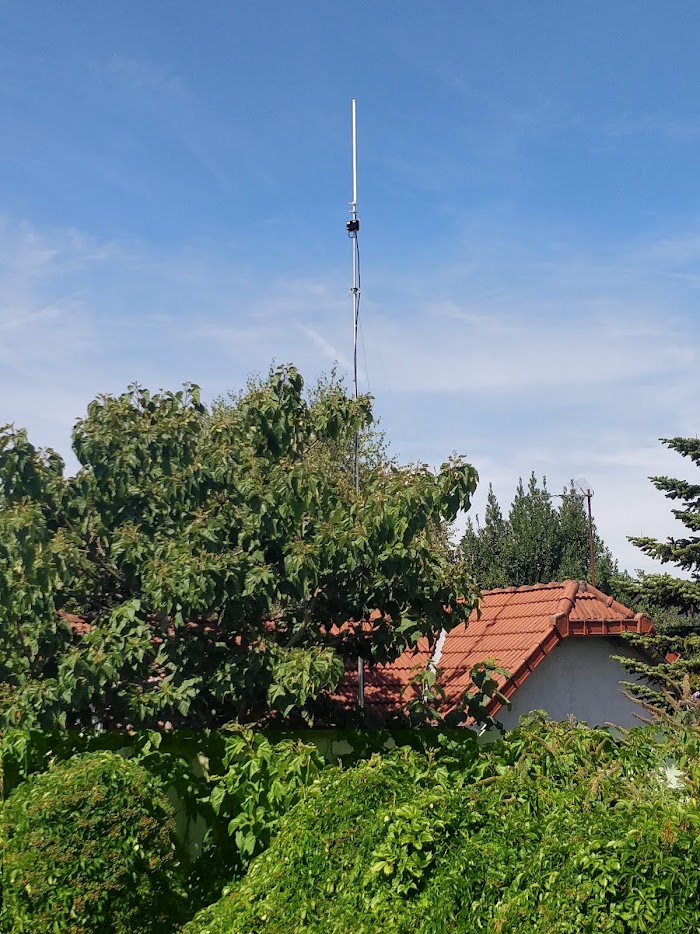
Everything in an antenna system is measured in decibels, and decibels are unforgiving: six of them halve your range. Most installations give away more than six through details that cost nothing to get right at design time and a site visit to fix afterwards.
Antenna Gain Is Not Free Range
An omnidirectional antenna does not create energy. Gain comes from reshaping the pattern, taking the radiation that a simple dipole sends uselessly upward and downward and squeezing it toward the horizon. A higher gain figure means a flatter, narrower beam.
That is exactly what you want on flat terrain, where every device is near the horizon from the gateway's point of view. It is exactly what you do not want on a tall mast covering a campus at its feet, or on a hillside above a valley full of sensors, because the devices below sit in the pattern's null. A high-gain antenna mounted high can deliver worse coverage close in than a modest one, and the failure is confusing because everything about the specification says it should be better.
The practical rule: gain for distance on flat ground, less gain when coverage is below you or the terrain varies. A 3 dBi antenna on a rooftop covering the surrounding neighbourhood frequently outperforms an 8 dBi one in the same spot. If you need both reach and near coverage, that is an argument for two gateways rather than one heroic antenna.
Polarisation belongs in the same conversation and is far less forgiving than gain. LoRaWAN devices are almost always vertically polarised, so the gateway antenna must be vertical too. Mounting one horizontally, or at a sloppy angle on a bracket nobody checked, throws away far more than any gain figure will ever recover. It is free to get right and it is checked by looking at it.
One more property, covered at length in the noise and filters article: a resonant antenna cut for your band is itself a filter, while the cheap broadband multi-band antennas marketed for cellular will deliver every strong transmitter in the area straight into your receiver. Specifying the right antenna prevents interference problems you then never have to diagnose.
Where the Decibels Actually Go
Coaxial cable loses signal per metre, and the difference between cable types at 868 or 915 MHz is not subtle:
| Cable | Loss per metre | 10 m | 20 m | 30 m |
|---|---|---|---|---|
| RG58 | ~0.55 dB | 5.5 dB | 11.0 dB | 16.5 dB |
| LMR-240 | ~0.25 dB | 2.5 dB | 5.0 dB | 7.5 dB |
| RG213 | ~0.19 dB | 1.9 dB | 3.8 dB | 5.7 dB |
| LMR-400 | ~0.13 dB | 1.3 dB | 2.6 dB | 3.9 dB |
Read the RG58 row again. Twenty metres of the thin black coax that comes coiled in the box with a cheap antenna costs 11 dB, which in a typical environment is roughly sixty percent of your range, gone before the first packet. The same run in LMR-400 costs 2.6 dB. The cable upgrade costs less than one site visit.
This loss is symmetrical and it applies to everything. It reduces your transmit power on downlinks and your sensitivity on uplinks equally, and unlike interference it is present at three in the morning on a quiet Sunday. It is also the reason a filter or a masthead amplifier belongs at the top of the feedline rather than the bottom.
Pigtails deserve a specific warning. The 30 cm of thin cable used to adapt between connector types looks trivial and can cost a decibel by itself, and installations routinely stack two or three of them. Count every adapter in the chain.
The cleanest answer to all of this is to have no feedline at all. Gateways with an integrated antenna, or designs where the radio mounts directly at the antenna, remove the largest single loss in a typical install and remove the connector that most often lets water in.
Connectors and Water
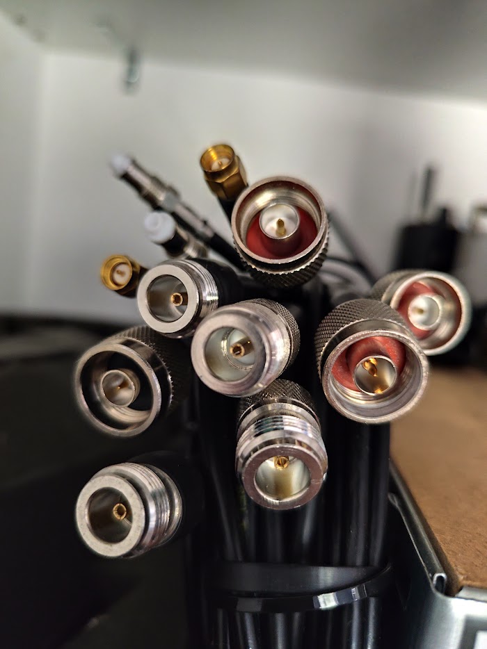
Outdoors, use N-type. It is designed for it, it survives being torqued properly, and it is far more tolerant of weather than the SMA connectors common on indoor equipment. SMA and RP-SMA look identical to anyone in a hurry and are not interchangeable, and mixing them wastes an afternoon on a roof.
Every outdoor connection needs sealing, and the method that works is unglamorous: wrap the mated pair in self-amalgamating tape, then over-wrap that with UV-resistant electrical tape to protect the amalgamating layer from sunlight. Leave a drip loop below every connector so water runs away rather than into it. Use UV-rated cable ties, because the cheap ones become brittle dust in two summers and drop your feedline.
Water in a connector is the classic slow failure. It does not stop the network, it degrades the match progressively over months, and by the time someone investigates, the deployment has been quietly losing range since the previous winter.
Height, and What Line of Sight Really Means
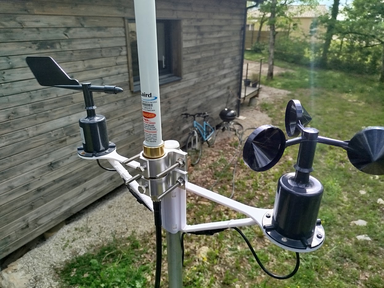
Height is the highest-value decision in any gateway installation, which is why the range assessment article puts it ahead of antenna gain. Ten metres of additional elevation regularly outperforms every other change available to you.
What is less well understood is that visual line of sight is not enough. Radio needs clearance around the direct path, in an ellipsoid called the first Fresnel zone, and obstacles intruding into it cause loss even when you can see straight over them:
| Link distance | Clearance needed at midpoint (868 MHz) |
|---|---|
| 1 km | 9.3 m |
| 2 km | 13.1 m |
| 5 km | 20.8 m |
| 10 km | 29.4 m |
A 5 km link needs about 21 metres of clearance above the treetops at its midpoint, not zero. This is why a gateway that can "see" a distant site still performs badly across a wooded valley, and why summer foliage changes a link that tested fine in February.
At the mast itself, keep metalwork away from the antenna. The wavelength is about 35 cm at 868 MHz and 33 cm at 915, and a metal pole within a quarter of that, under 9 cm, distorts the pattern measurably. Standoff brackets exist for this reason. Elevation also means wind loading, so guy the mast properly: an antenna that swings is an antenna whose pattern moves, and a mast that fails takes the gateway with it.
Most Dead Gateways Die Through the Ethernet Cable
This surprises people, so it is worth stating plainly. Elevated installations do occasionally take a direct lightning strike, and nothing you can reasonably fit will save the equipment if they do. What actually kills gateways, routinely, is induced surge from a nearby strike, and it usually arrives through the data and power cabling, not the coax.
A gateway on a mast is connected to a long copper Ethernet run into a building. That run is an excellent antenna for the electromagnetic pulse of a strike hundreds of metres away, and it delivers that energy directly into the gateway's Ethernet port and, often, onward into the switch it is plugged into.
Protection is layered and none of the layers are expensive. Fit a coaxial surge arrestor, typically a gas discharge tube type, where the feedline enters the building or at the base of the mast, and bond it to a proper earth. Bond the mast itself. Protect the Ethernet run with an appropriate surge protector at the building entry, and where the budget allows, use fibre for the backhaul, which is immune to all of this and removes the copper path entirely. Ground everything to a single point, because two separate earths at two ends of a cable create a ground loop that can be worse than no protection at all.
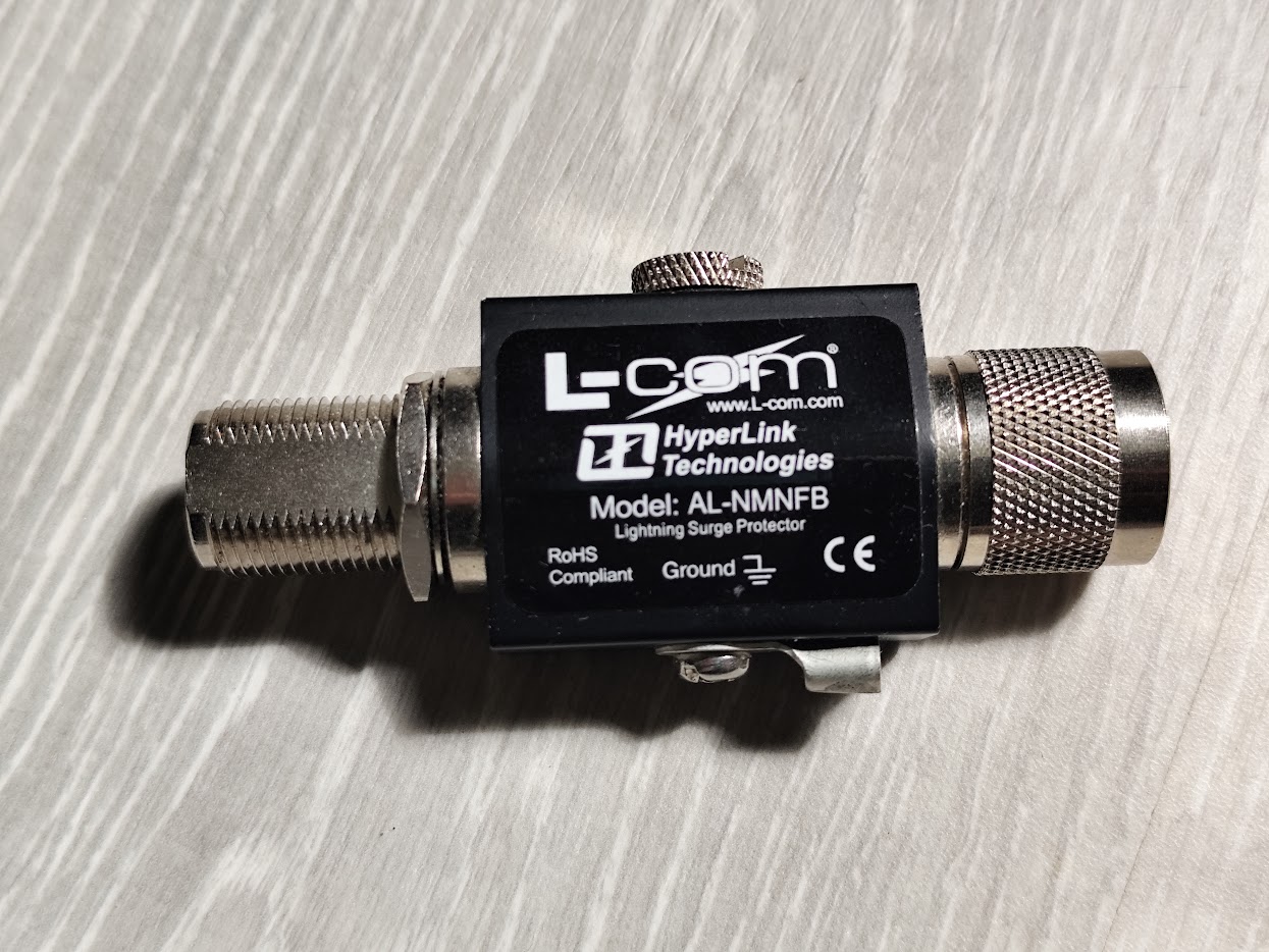
None of this is exotic and all of it is standard practice in radio and telecom installation. It is simply outside the experience of most IoT teams, who correctly think of themselves as working on a software project until the day a thunderstorm removes three gateways.
Prove the Install Before You Leave
Everything above is a design decision. The install itself should be measured, and a handheld vector network analyser makes this a five minute job.
Disconnect the feedline at the gateway end and sweep it with the antenna attached, looking at return loss across your whole band. Better than 15 dB of return loss, meaning a VSWR under about 1.4, is a healthy antenna system. Anything much worse than that has a problem worth finding now, while you are still on site with tools, rather than in a year when someone notices the coverage map has shrunk.
A sweep also identifies what is wrong, not just that something is. A crushed cable, a badly terminated connector, water ingress, and a damaged antenna element all have different signatures, and a baseline sweep recorded at commissioning turns every future measurement into a comparison rather than a guess. Recording that baseline costs nothing and is the single most useful piece of documentation an installer can leave behind.
What Each Mistake Costs
| Mistake | Typical cost |
|---|---|
| 20 m of RG58 instead of LMR-400 | 8.4 dB |
| Two or three stacked adapter pigtails | 1 to 3 dB |
| Water in an unsealed connector | 3 dB and rising |
| High-gain antenna over close-in coverage | severe, near the gateway |
| Horizontally mounted antenna | 20 dB and unpredictable |
| Obstructed Fresnel zone | 6 to 20 dB, seasonal |
| No surge protection on the Ethernet run | the gateway |
Six decibels halves your range. Most of that table is avoidable at zero marginal cost during design, and expensive to correct once a mast is up and an installer has gone home.
What I Provide
The antenna system is where deployments quietly lose the performance they paid for, and it is the part of a LoRaWAN project most likely to be specified by whoever was ordering the gateway rather than by anyone thinking in decibels.
I specify and validate the whole RF chain: antenna selection matched to the terrain and coverage pattern you actually need, feedline and connector specification with the loss budget worked out in advance, mast and mounting arrangements, and surge protection that reflects how gateways really die. Installations get swept and documented with a baseline measurement, so future troubleshooting starts from data instead of speculation.
That work sits alongside coverage surveys, interference diagnosis, and the rest of the deployment, and everything is handed over with measurements, documentation and source code. There are no recurring fees. If a gateway is underperforming and nobody can say why, the answer is usually in the twenty metres between the receiver and the sky.
Working on a LoRaWAN project?
If this article touches on something you're building, tell me about it. The first conversation is free, and you'll get an honest read on the right approach for your situation.
Book a Free ConsultationCurious what the finished thing looks like? Open the live demo dashboard